Challenges in the renewal of medium-voltage switchgear and transformers during operation
Avangard Malz is a food manufacturer based in Gelsenkirchen, Germany. Avangard Malz produces a wide range of malt products and, with an annual output of around 340,000 tons, is the largest malting group in Germany.
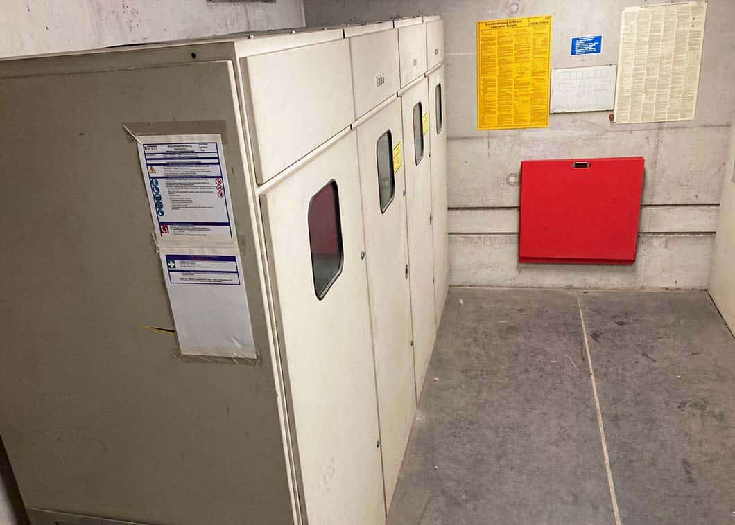
A 40-year-old, 8-bay air-insulated medium-voltage switchgear (MSP system) was used to supply power to the production facility, where the availability of spare parts was becoming critical and the function of the transfer circuit breaker was no longer given.
The function of the transformers (2 x 1,000kVA) was given, but they were very uneconomical due to the old loss class.
The challenge in renewing the plant was that it was not possible to switch off the transformers, as the supply to production had to be available at all times.
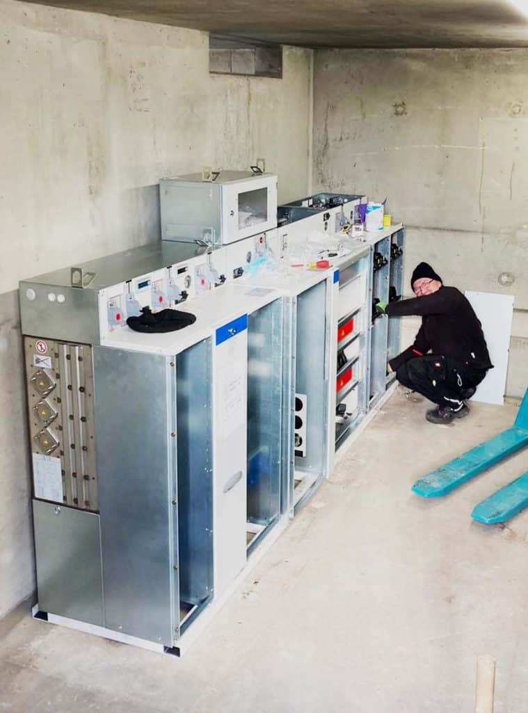
Figure 1: Part of the medium-voltage switchgear to be replaced
Temporary power supply through one of our rental stations
With more than 250 transformer stations of our own, we can quickly deliver a suitable solution for a wide variety of needs. This also includes the transitional power supply until the actual plant is completed.
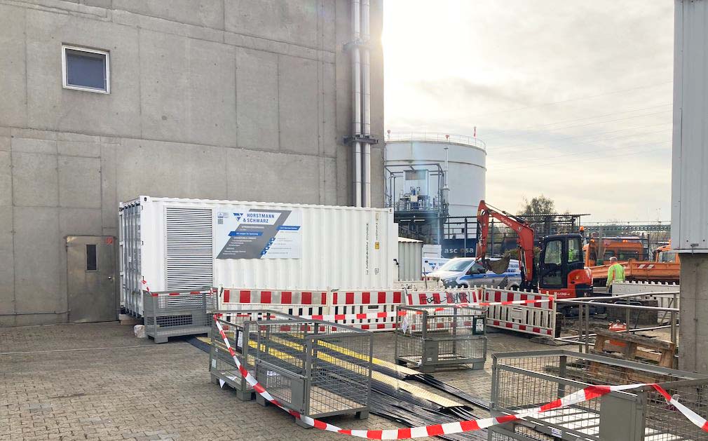
To ensure the power supply of the production of Avangard Malz during our conversion work, we used one of our rental container transformer stations with 2,000kVA and 2 outlets of 1,600A each. Temporary cable connections (borrowed cables from H & N Energien GmbH) were connected to each of these two outlets.
Preparations and conversion
Having already replaced an MSP system, a low-voltage main distribution (LVM) and the associated transformers in recent years, we were now due to replace the MSP system and transformers of the second station.
We replaced the 40-year-old, 8-field air-insulated old system with an SF6-insulated, 7-field Ormazabal system in accordance with DIN VDE-AR-N 4110.
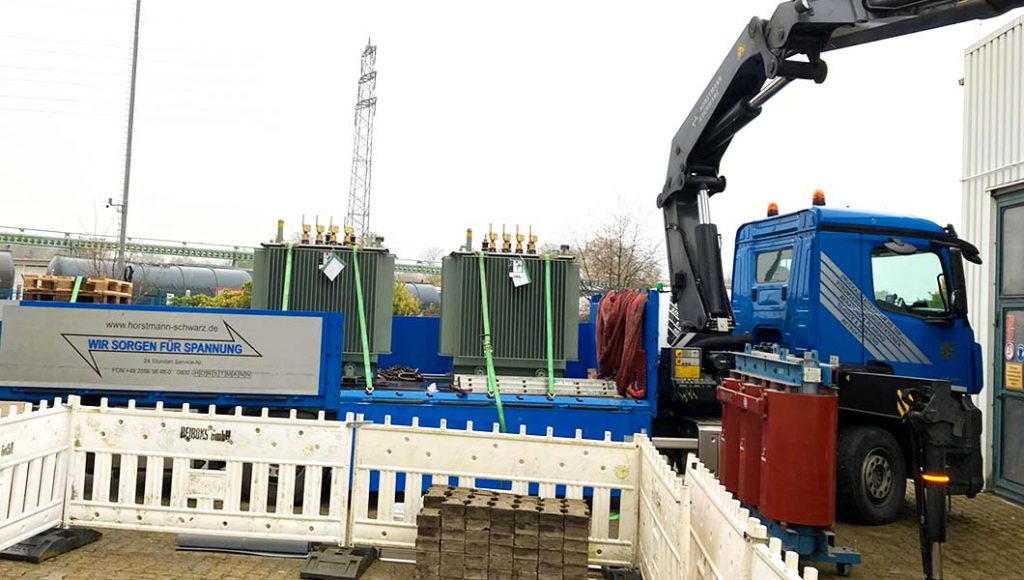
The two 1,000kVA cast resin transformers, which had become uneconomical due to their old loss class, were replaced by oil transformers. with greatly reduced open-circuit and short-circuit losses acc. Ecodesign Directive Stage 2 replaced from 01.07.2021.
Figure 2: Setting up our rental transformer station
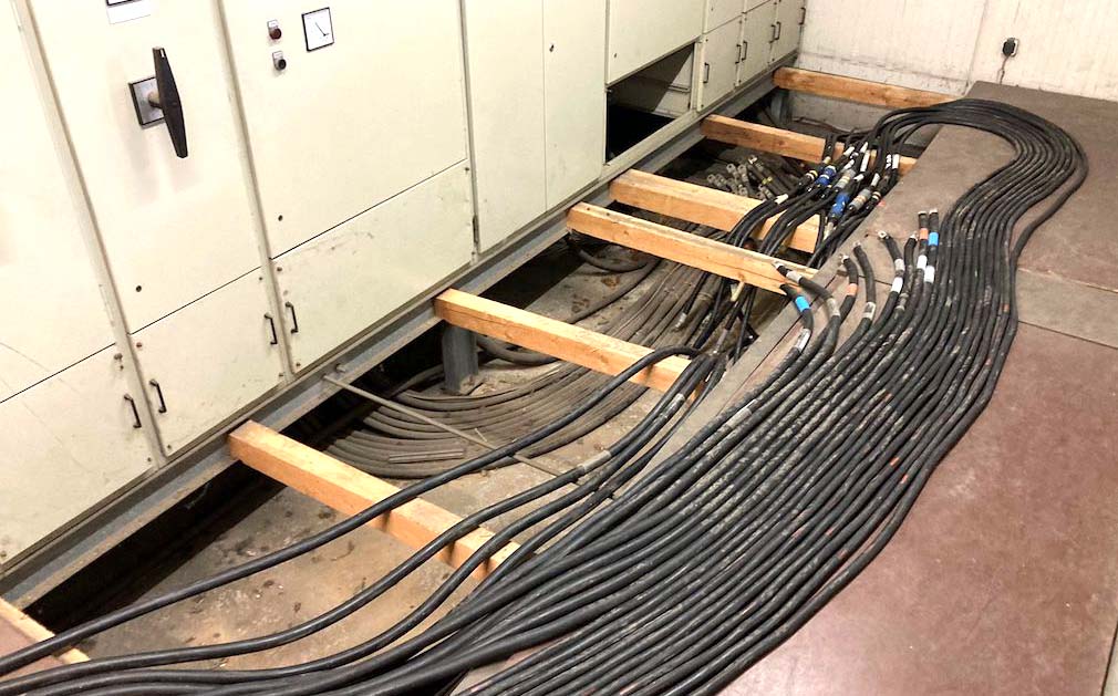
Figure 3: Laying of two cable systems each 1,600A for temporary power supply
The procedure during the changeover
Reduction of the total load of the existing transformers by Avangard to <50%.
MSP-side disconnection of transformer 1 (old plant), NSP-side disconnection of transformer 1 and NSHV (old plant).
NSP-side connection of the rental transformer station below the existing low-voltage circuit breaker transformer 1 (see Fig. 3).
Checking phase and frequency equality between LV/LV in rented transformer station and existing LV/LV
Connecting the temporary cable connection between the leased transformer station and the old NSHV system.
Repeat the steps for transformer 2 (second temporary cable connection)
After complete load takeover by rented transformer station: start with renewal of transformers and MSP system
After completion of the conversion work: successive connection of the new transformers and MV system (reverse sequence as described above).
Fig. 4: Delivery of the new oil transformers
End result: safer power supply with more economical transformers
Before the conversion, safe shutdown was no longer guaranteed in the event of a fault, which could result in danger to switchgear personnel, the building and the plant. In addition to personal injury and property damage, there was a major risk to ongoing operations.
In addition, no spare parts were available for the old plant and therefore no repair was possible.
The new system now complies with the latest DIN VDE AR-N 4110 standards with an arc fault resistance IAC AFL of 20kA, 1s, as well as IEC 62271-200.
An equally positive side effect: The reduced no-load and short-circuit losses increase the efficiency of the power supply enormously. Furthermore, in addition to being more efficient, the new transformers are also audibly quieter than the previous ones.
Savings potential in figures
Even more precisely, how much loss energy is really saved by the new transformers? Our sample calculation provides information.
For the old transformers built in 1982 (1,000kVA each), total losses amount to approx. 14.78 kW per transformer. By comparison, with the same rated power (1,000kVA each), the new transformers have a total power loss of only 8.29 kW per transformer – just under half.
For our customer, this means the following:
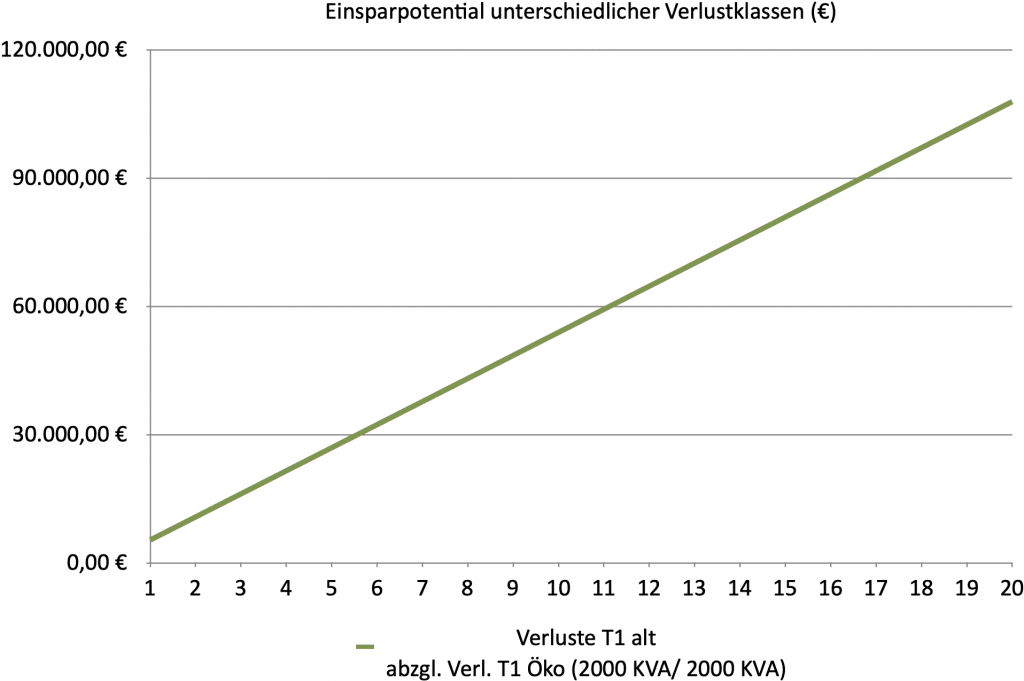
Continuous three-shift operation means a permanent load for the transformers. For the calculation we have assumed a permanent load of 60-70%. Calculated with an assumed electricity price of 0.10€/kWh, this results in an enormous savings potential over a period of 20 years, as the following graphic illustrates.
The return on investment thus occurs even before half of the imputed service life of approx. 35-40 years of the new station.
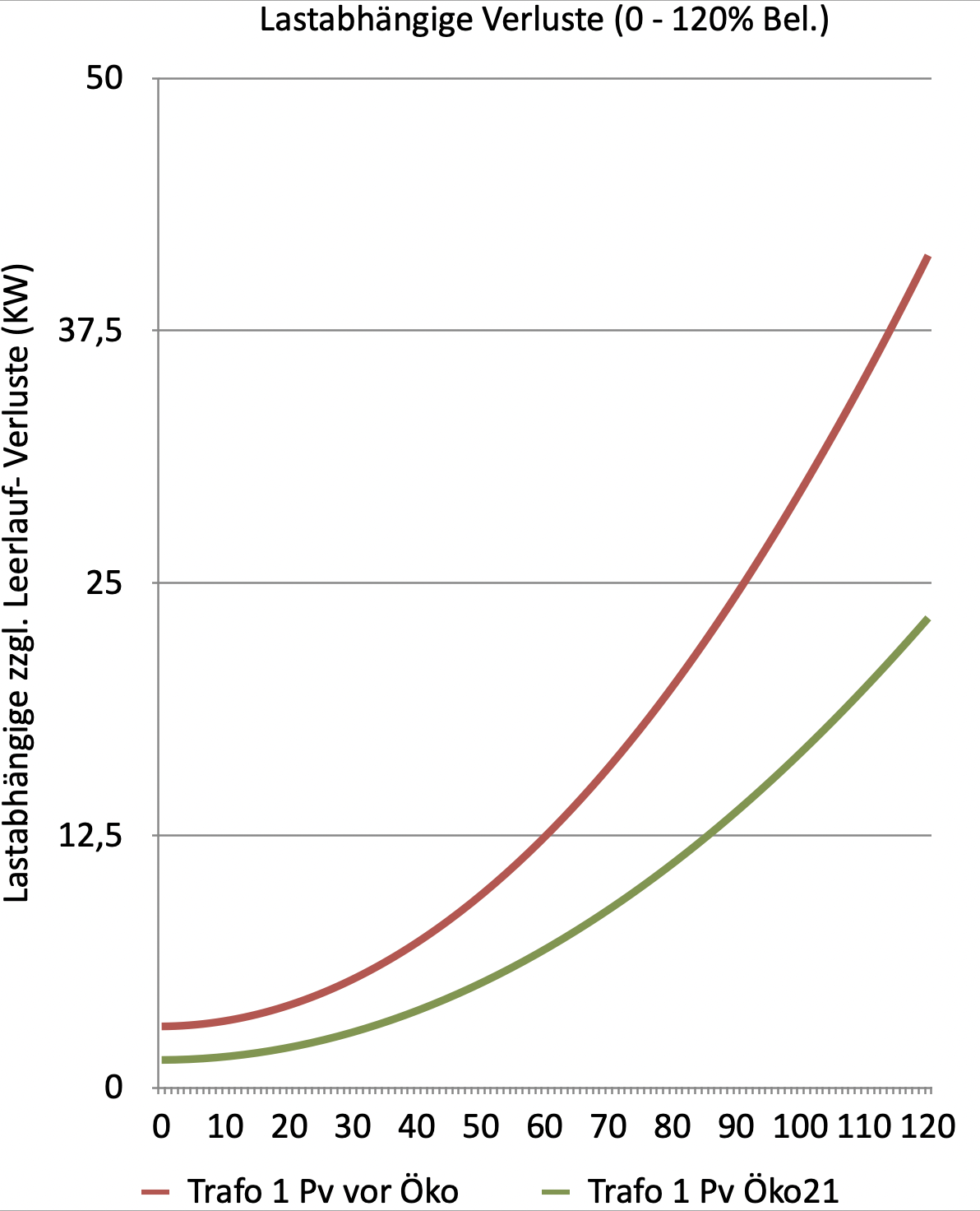
Transformer losses: The unavoidable losses of the transformers consist of short-circuit (load-dependent) and no-load (load-independent) losses. No-load losses are often also referred to as eddy current losses, hysteresis losses, or iron current losses. Short circuit losses are caused by the resistance of the coils. When a secondary current (load) flows, a voltage drop occurs and the windings of the coils heat up. The amount of losses increases quadratically with increasing load. The losses are also dependent on the transformer power. Before each transformer replacement, we therefore check the optimum operating point to determine the best possible transformer size for the required power.
Pv= load dependent power loss
No-load losses, on the other hand, are caused by the constant remagnetization of the iron core. The transformer manufacturer can exert a positive influence through the quality of the core laminations and optimum transitions between the individual laminations. A good transition also optimizes noise emissions. The thickness of the plates also has an influence: Particularly thin rolled plates minimize the losses.
Would you like to know how much savings potential is possible for your company with a modernized or new transformer station? We will be happy to advise you.